Guidance for Hose & Coupling Assembly
The Hose and Coupling Assembly Instructions provide guidance to support safe and consistent assembly of approved hydraulic hose and coupling assemblies for workshop and on-site environments.
First - hidden
Your content goes here. Edit or remove this text inline or in the module Content settings. You can also style every aspect of this content in the module Design settings and even apply custom CSS to this text in the module Advanced settings.
1. Safety Procedures
1.1 Wear eye protection where necessary.
1.2 Wear hearing protection when operating noisy equipment.
1.3 Take care when using cutting tools.
1.4 Loose fitting clothing should not be worn near moving or rotating equipment.
1.5 Work in well ventilated, well lit areas.
1.6 Keep appendages clear of moving parts.
1.7 Crimping equipment is able to generate forces of many tonnes, keep hands well clear of crimp zone. (Refer to RH-WI-101)
1.8 Do not mix and match hose and couplings from various manufacturers.
1.9 Do not reuse hose coupling components unless reuse is specifically authorised by the manufacturer. (Field attachable couplings may be reused only once and only where they have not been subjected to forces outside the range of general use.)
1.10 If cutting hose that has been in service, the fluid that has been in the hose may cause toxic fumes when cut. Wear breathing protection where necessary.
1.11 Make sure that equipment is securely mounted and in a serviceable condition efore use.
2. Cutting Hose
Equipment used to cut hoses includes:
2.1 Hand tools
a) Knives
b) Hacksaws
2.2 Power cut off saws
a) with Steel blades
b) with Abrasive blades
c) guillotines
Methods and equipment appropriate to one hose style may not be appropriate to another hose style.
The most important aspect of cutting hose is that the cut must be neat and square to the axis of the hose. Refer to diagram below.

Cut the hose as squarely as possible within the following limits:
- Not more that 1.5mm out of square for sizes up to 25mm.
- Not more that 2.0mm out of square for sizes 26 mm up to 51mm.
- Not more that 3.0mm out of square for sizes above 51mm.
Ensure any protruding wires remaining after the cutting process are carefully and safely removed by manually cutting and / or grinding them away to eliminate the risk of injury during handling processes.
Other considerations in the cutting of hose include:
1. The amount of residue or particles left inside the hose after the cutting process;
2. Flaring or crushing of the reinforcement in the cutting process;
3. Cleanliness of cut;
4. Noise, smoke, smell, fumes generated by the cutting process.
Hose assembly length specifications:
Unless otherwise specified the hose assembly length tolerances as per below Table 3 excerpt from SAE J517 shall apply:
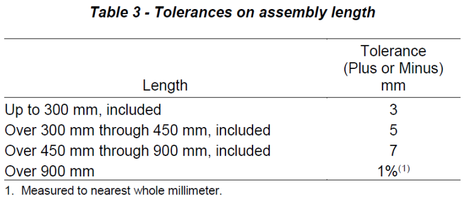
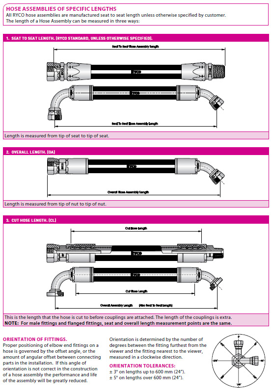
Refer below for assembly length mesurement methods and standard angular orientation mesurement for elbow fittings. Unless otherwise specified by customer orders, hose assembly lengths are measured from seat to seat.
3. Cleaning Bore of Hose
After the hose is cut, there will be rubber particles, reinforcement particles or cutting grit in the bore; the bore must be cleaned.
An appropriate method of cleaning should be chosen depending on the intended application of the hose assembly, or the customer’s specifications for cleaning.
3.1 For all hose assemblies, use a foam cleaning pellets propelled through the hose with compressed air. Hose bore shall be inspected to ensure the cleaning pellet has exited the hose.
3.2 Upon customer request, use compatible fluid flushing method.
3.3 Hose assemblies used in applications relevant to MDG41 MUST have a foam cleaning projectile shot through the hose from both ends. Hose bore shall be inspected to ensure the cleaning pellet has exited the hose.
4. Skiving of Hose
In some cases, to allow proper installation of hose couplings, the outer protecting cover of wire reinforced hose must be carefully removed to the wire at the end of the hose. For some couplings, a short length of the inner tube must also be removed at the end of hose.
Removing the cover is called EXTERNAL SKIVING, and removing the inner tube is called INTERNAL SKIVING.
There are three basic methods of externally skiving a hose
1. By hand tools;
2. By Wire Wheel method;
3. Specialised skiving equipment.
NOTE: Internally skiving requires the use of specialised equipment.
With any skiving method, it is important to ensure that the cover and / or tube are removed over the correct skive length, and that the wire reinforcement is not displaced, damaged or cut in the process. Failure to completely remove the cover and / or tube, or damage to the reinforcement, may result in deficient hose coupling attachment that could lead to failure.
- If external skive length is too short, the ferrule may not be able to grip the hose correctly.
- If external skive length is too long, the end of the ferrule may not weather seal correctly onto the hose cover.
- If internal skive length is too short, the insert may not be able to be fully inserted.
- If internal skive length is too long, the insert may not locate or seal correctly.
Refer to Ryco Crimp App and Web Tool for correct skive length.
4.1 By hand tools
a) Clamp the hose in a vice or other suitable holding device. Ensure that the hose is not crushed or damaged by the holding device.
b) Mark the skive length on the outside cover of the hose.
c) Cut through the cover, around the circumference of the hose at the skive length mark, down to the wire.
d) Cut through the cover down to the wire; starting at the circumference cut, along the hose skive length to the end of the hose.
e) Peel back the hose cover in the skive section, or cut the skive section away.
f) Check that all cover has been removed.
4.2 By Wire wheel
a) Mark the skive length on the outside cover of the hose.
b) Mark the cover diametrically around the hose at the skive length.
c) Rotate the hose against a wire wheel to remove the cover.
d) In some instances, with care, the hose may be hand held while being wire brushed.
4.3 By specialised skiving equipment
a) Select correct skiving tool for the skive length and diameter required.
b) Ensure skiving tool is sharp and properly adjusted.
c) Put skiving tool in chuck of lathe or machine to be used.
d) Ensure appropriate safety guarding is in place.
e) Select clockwise direction of rotation of the chuck when skiving cover of spiral reinforced hoses.
f) Select anti clockwise direction of rotation of the chuk when skiving inner tube of spiral reinforced hoses.
g) Ensure mandrel part of skiving tool is lubricated.
h) Lubricate hose ID if necessary.
i) Start the lathe or machine.
j) Carefully align hose onto mandrel.
k) Apply steady pressure and start mandrel into hose.
l) When cutting head or edge contacts hose end, head or edge will cut cover or tube from hose until hose bottoms against stop.
m) Continue to operate machine and pull hose back off mandrel.
n) Check that all cover or tube has been removed. If necessary, repeat steps j) to m).
5. Mark Length for Non Skive Hoses
This is not visible by an external inspection of non-skive hose.
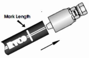
Prior to inserting the coupling, a mark is made on the cover of the hose, refer below. The coupling must be pushed into the hose until the edge of the ferrule is in line with the mark to ensure full insertion has been achieved.
The mark length also allows for inspection after the ferrule is crimped to ensure that the coupling has remained fully inserted onto the hose during the crimping operation.
Obtain mark lengths from the latest version of RH-WI-61 Crimp Chart available at following web site https://www.ryco-hydraulics.com/product-literature/
For Ryco hose & coupling combinations go to Ryco Web site: https://www.ryco-hydraulics.com/ and log into the Ryco Crimp Web Tool.
6. Assembly / Inspection Instructions
6.1 Determine the correct mark length from the current version of Crimp Chart Document No. RH-WI-61. (Or if applicable the relevant Manuli crimp chart)
6.2 Make an indelible, visible mark on the cover of the hose at the mark length distance from the end of the hose.
6.3 Push the coupling onto the hose so that the edge of the ferrule is in line with the mark.
6.4 Crimp the coupling to the required diameter in accordance with current crimp chart.
6.5 Measure diameter with a calibrated vernier caliper or micrometer to ensure the correct crimp diameter has been achieved.
6.6 Inspect crimped coupling to ensure that the mark has remained in line with the edge of the ferrule to ensure full hose penetration length has been achieved.
6.7 Visually and dimensionally inspect hose assemblies in accordance with Document No. RH-WI-70 to ensure all couplings have been crimped correctly and to ensure the couplings are free from any mechanical defects.
6.8 Dimensionally inspect assembly length to ensure it is within SAE J517 hose assembly length tolerances unless otherwise specified by job / customer order or other applicable specification.
6.9 Ensure hose cover is clean and free from contamination or scuff marks.
6.10 MDG41 applicable and Type Approved Hose Assembly (such as DNV) inspections should also include:
a) Labelling is true and correct. NOTE: If SS metal ID tag is required (as may be the case with some Naval or DNV requirements) ensure it is fitted after testing and after any outer sleeving has been installed,
b) Assembly condition is free from kinks, loose covers, bulges or ballooning, soft spots, cuts, broken or protruding wires, any other obvious defects,
c) Fittings and attachments are securely crimped or fastened, correct for hose size, series or type, free from cracks, not cocked, free from bulges where they join the hose, free to swivel, free from rust,
d) The assembled hose corresponds to the order requirement,
e) The assembled hose is free from contaminants, hose ends are capped, plugged and the hose is packed correctly for transport.
Note: Where practical the person carrying out the visual inspection should be different to the person who assembled the hose.
7. Proof Testing of Assembly
If internal proof pressure testing is required, the following steps shall be taken.
7.1 Connect hose assembly to suitable pressure test rig or pump using the appropriate adaptors. (IN A SAFETY ENCLOSURE or A SAFE ENCLOSED AREA).
7.2 Tighten couplings / adaptors and thoroughly bleed hose of air.
7.3 Raise internal pressure to two times the hose assembly working pressure, unless other specified by customer or industry standard.
7.4 Test pressure should be held for a minimum of 30 seconds and maximum of 60 seconds, unless otherwise specified. There should be no indication of failure or leakage.
7.5 Visually inspect the assembly while it is under pressure for any evidence of leakage, cracking, abrupt distortion indicating irregularity in materials or manufacture, or any other evidence of failure.
7.6 If the hose integrity has not changed and there was no leakage, the assembly shall be considered as passed.
7.7 Document the results on job records to allow for generating test certificate if requested.
8. Third Party Type Approved Hose Assemblies
Note:- Testing should be carried out prior to fitting any sleeving
8.1 Unless otherwise specified, hose assembly testing shall be carried out in accordance with current version of ISO 1402.
8.2 Unless otherwise specified by customer order or regulatory authority such as DNV, LR, ABS, BV etc…, the proof test pressure shall be twice the hose assembly rated working pressure.
Note: Consideration should be given to proof testing all hose assemblies at two times the rated working pressure to minimise risk of hose assembly failure and injury.
8.3 Unless otherwise specified the test pressure should be held for a minimum of 30 seconds and maximum of 60 seconds.
8.4 Visually inspect the assembly while it is under pressure for any evidence of leakage, cracking, abrupt distortion indicating irregularity in materials or manufacture, or any other evidence of failure. There should be no indication of failure or leakage.
8.5 Proof testing should be carried out using compatible hydraulic fluid or water. Do not use compressed gases.
9. Individual Hose Assembly Test Documentation
MDG41 Applicable Hoses and Third Party Type Approved Hose Assembliles such as DNV; ABS; LR; BV…
9.1 Individual Hose Assembly Test Documentation
Each test certificate should bear a unique number for traceability. Test certificates should include the following information as required:
a) Test certificate number
b) Testing location and name
c) Test procedure reference number
d) Assembler’s name
e) Fabrication number (if applicable)
f) Hose assembly part-number and / or serial number(s)
g) Hose assembly details including length, type of hose and size
h) Hose assembly standard
i) End fitting details that can identify types of ferrules and seals used
j) Test date
k) Confirmation that the hose assembly consisted of matched hose and hose ends
l) Hose end information and check for correct matching of hose ends to hose
m) Test pressure
n) Pass / fail
o) Signature of person inspecting
NOTE: For DNV Type Approval (or other TA such as ABS, LR, BV etc…) the Type Approval certificate number shall be listed on the test certificate.
10. Batch Certificate of Conformance
MDG41 Applicable Hose Assemblies
10.1 A certificate of conformance should be supplied when requested. The certificate of conformance should have the following information, if applicable:
a) Customer’s name, address, purchase order, contact details
b) Specification, drawings and standards the assembly conforms to
c) Supplier’s name, address, purchase order, contact details
d) Supplier’s order number
e) Description and quantity of supply
f) Additional information as requested
g) Supplier’s authorisation Signature
h) Date of supply
11. NATA Test Report
(Applicable to Branches with NATA ISO 17025 approval)
11.1 The NATA pressure test report certificate shall list the following.
- Title of test: “Hydrostatic Pressure Proof Test Report”.
- Name and address / location of the branch test facility.
- Pressure gauge / transducer serial number and calibration reference.
- The customer’s name and address details.
- Test method reference.
- Description of the hose assembly tested.
- Test date.
- Test certificate / report issue date.
- Test pressure.
- Ambient environmental temperature.
- Test result.
- Name of person authorising the test certificate report.
- If applicable, any deviations from the test standard shall be listed.
- The following statement: “The results of this test certificate report relate only to the item description mentioned. This document shall not be reproduced except in full.”
The test certificate shall be signed by the test lab operator and reviewed and approved by an approved NATA signatory who is authorised to sign the declaration of conformity before issuing the test certificate to the customer.
12. Cleaning & Packaging
MDG41 Applicable and Third Party Type Approved Hose Assemblies such as DNV; ABS; LR; BV, etc.
12.1 Hose assemblies should be supplied free from water, debris, metal shavings,
dirt or any other foreign material.
12.2 Hose bore shall have been cleaned with a foam projectile pellet being shot through the hose assembly in both directions via high pressure air. Hose bore shall be inspected to ensure the cleaning pellet has exited the hose.
12.3 End connections should be sealed and capped to maintain cleanliness.
12.4 Hose assemblies should be packaged such that external abuse during shipping, handling and storage does not damage the hose or fittings.