Guidance for Safe Operations
Safe Operation of Crimping Machines supports correct setup, awareness of operating requirements, and safe working practices during hose assembly activities.

The following instructions provide recommendations for the safe use of Crimping Machines.
Warning:
Eye Protection, such as Safety Glasses or a Face Mask must be worn when operating crimping machines.
First - hidden
Your content goes here. Edit or remove this text inline or in the module Content settings. You can also style every aspect of this content in the module Design settings and even apply custom CSS to this text in the module Advanced settings.
1. Scope
This procedure applies to most crimper types and should be adopted by personnel who fabricate hose assemblies regardless of their position, location or frequency of assembly.
2. Procedure
To minimise the chances of injury, SAFETY ZONES must be identified and implemented around the crimp dies (refer Figure 1). The SAFETY ZONES incorporate two areas, an EXCLUSION ZONE, and a CAUTION ZONE.
Figure 1
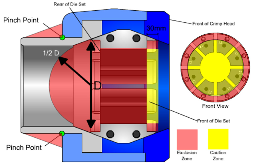
2.1 Definition of “Exclusion Zone”:
The Exclusion Zones, (the red shaded areas in Figure 1), represent areas where there is a direct risk of a crushing injury to the operator. Hands, tools and other items must be kept well clear of these areas during operation of the crimping machine.
2.2 Definition of “Caution Zone”:
The Caution Zone, (the yellow shaded area in Figure 1), represents an area where there is minimal potential of injury to the operator. However a potential for injury is considered to exist due to the close proximity of this area to the Exclusion Zone. For this reason, it is recommended that hands are kept clear of the Caution Zone whenever possible. Operators hands may enter the Caution Zone once the risk of injury to the operator has been minimised.
The methods of minimising this risk are outlined in section 3.4 – Safe Operation.
2.3 Identification of exclusion zones (refer Figure 1).
Regardless of the crimping machine make, type or design, body parts or foreign objects MUST not contact the crimping dies or master dies. Note that the design of some machines means that the jaws also move axially during the crimping process. Allow for axial movement when keeping hands clear of moving parts.
Front of die set
A zone at the front of the crimp head within 30mm of the die face. On many machines the master dies move axially during the crimping process, the result is that both the Exclusion Zones and the Caution Zone also move in relation to the crimp head. In many cases, the master dies will protrude from the front face of the machine as the dies close. This creates potential pinch points around the perimeter of the master dies.
Rear of die set
The zone at the rear of the crimp dies within a theoretical hemisphere defined by the actual diameter of the rear opening. Adopting a defined Exclusion Zone at this point reduces the possibility of injury to hands entering the machine from the rear.
Middle of master dies
The zone between the “Front of die set”, and “Rear of die set” areas as previously defined.
Outside face of sliding piston rod
There is a possible pinch-point hazard between the main housing and the outside surface of the sliding piston rod.
Note: On some machines, the R32 for example, there is a flange fitted to the rear of the sliding piston rod. This is to allow the piston rod to be returned by hydraulic cylinders. Earlier model machines are unguarded, whilst later model machines have a sheet metal guard fitted to prevent hands being placed upon the rod, or between the rod and the housing. Fitted guards must not be removed, or tampered with in any way.
2.4 Safe Operation
The majority of these machines incorporate a slow die movement with semi-automatic operation. Semi-automatic operation means that the dies will stop moving when the operator releases the “Die Close” button. This means that the operator is in complete control of the die movement.
The machine movement is considered to be controlled. Therefore, an operator may position his or her hand within the Caution Zone during operation, but only when:
- Total machine controllability has been established.
- The operator is fully alert and is not distracted in any way.
- The person positioning the assembly within the dies is the only person in control of the machine.
- The position of the operator’s hands are fully visible to the operator at all times.
IMPORTANT:
If the operator’s hands are placed close to the dies during the crimping operation, (i.e. within the Caution Zone), the recommended practice is one where the machine is “jogged”.
This means that the dies are brought to a close in short controlled steps. This will give the operator the control necessary to monitor the machine movement thereby ensuring safe operation.
If a machine has a rapid approach or retract function, (e.g. R51 model), hands should be kept as far as possible from the die area at all times.
General Rule:
Support the hose assembly from a position outside the machine area where possible. The further you are from the dies, the further you are from potential injury.
3. Crimping Method
Due to the design of Ryco couplings, the entire ferrule must be crimped in one operation (refer Figure 2).
CRIMPING COUPLINGS
Couplings MUST be crimped over the whole length
Of the ferrule including the nose crimp where the ferrule Is attached to the insert.
Figure 2

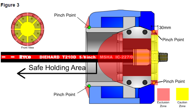
3.1 Rear Insertion Method
Due to the necessity of correctly positioning the ferrule collar within the crimping dies, and the obvious importance of operator safety, one recommended method is inserting the hose from the rear of the machine (refer Figure 3).
This practice allows the position of the coupling ferrule nose crimp to be more easily viewed, whilst keeping the operator’s hands at a safe distance. The supporting hand must be outside of the Exclusion Zone at all times, and should be visible to the operator whenever practical.
Figure 3
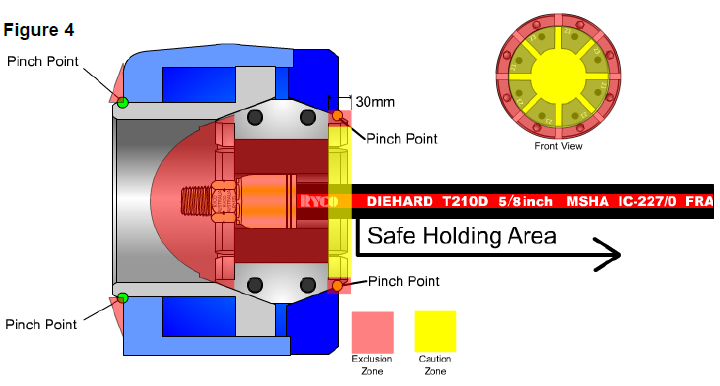
3.2 Front Insertion Method
A second assembly method is one where the hose is inserted from the front of the machine (refer Figure 4). This method ensures the safe placement of hands during the crimping operation, thereby reducing the risk of the operator placing his or her hands within the rear exclusion zone.
Figure 4
IMPORTANT:
Extra care must be exercised when crimping with this method, as it can be more difficult to verify that the coupling is correctly positioned within the dies.

In some cases, straight end style couplings with small ends will allow the coupling to be safely crimped without an accurate prior positioning of the coupling within the crimp dies.
In such cases, the ferrule can be crimped anywhere within the length of the dies, as long as the full ferrule is crimped in one operation (refer Figure 5).
In these cases where the dimensions of the coupling end style negate the need for accurate coupling positioning within the crimping dies, the front insertion method is the preferred method.
4. Safety Warnings
Be aware of the published warnings stated explicitly on the crimping machine, in the corresponding crimping machine operating manual, and in other crimping machine documentation. The labels shown in Figure 6 must be legible on the front face of the crimping head. Note that older model machines may only have Warning 1 displayed, this is sufficient in alerting operators to a potential hazard.
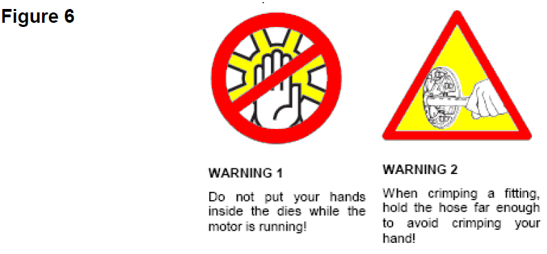
These two warnings are the basis for the safe operation of any crimping machine.
5. Machine Limitations
The R16 and R51 machines limit both the insertion direction of the hose, and the maximum crimping force available for a given diameter.

There is a statement in the manual outlining that hoses should be fed in from the front only, and this directive is re-affirmed by a permanent label on the crimping head. This operational limitation arises from the crimper Die Cone design.
Always follow the manufacturer’s directions in this regard.
6. Maintenance & Calibrartion
Crimpers must be regularly inspected and maintained to ensure safe and effective operation. Any electrical works or repairs like changing seals or the pump must only be carried out by a qualified specialist.
Crimpers must also be regularly calibrated to ensure accurate and effective crimps.
7. Conclusion
The Ryco crimping machines present very minimal risk to operators. As with any machine, there is a potential of risk to an operator if due care is not shown.
If the machine shows signs of erratic operation or unexpected movement, remove the machine from service immediately and consult the Ryco technical support.